Beginning frame assembly

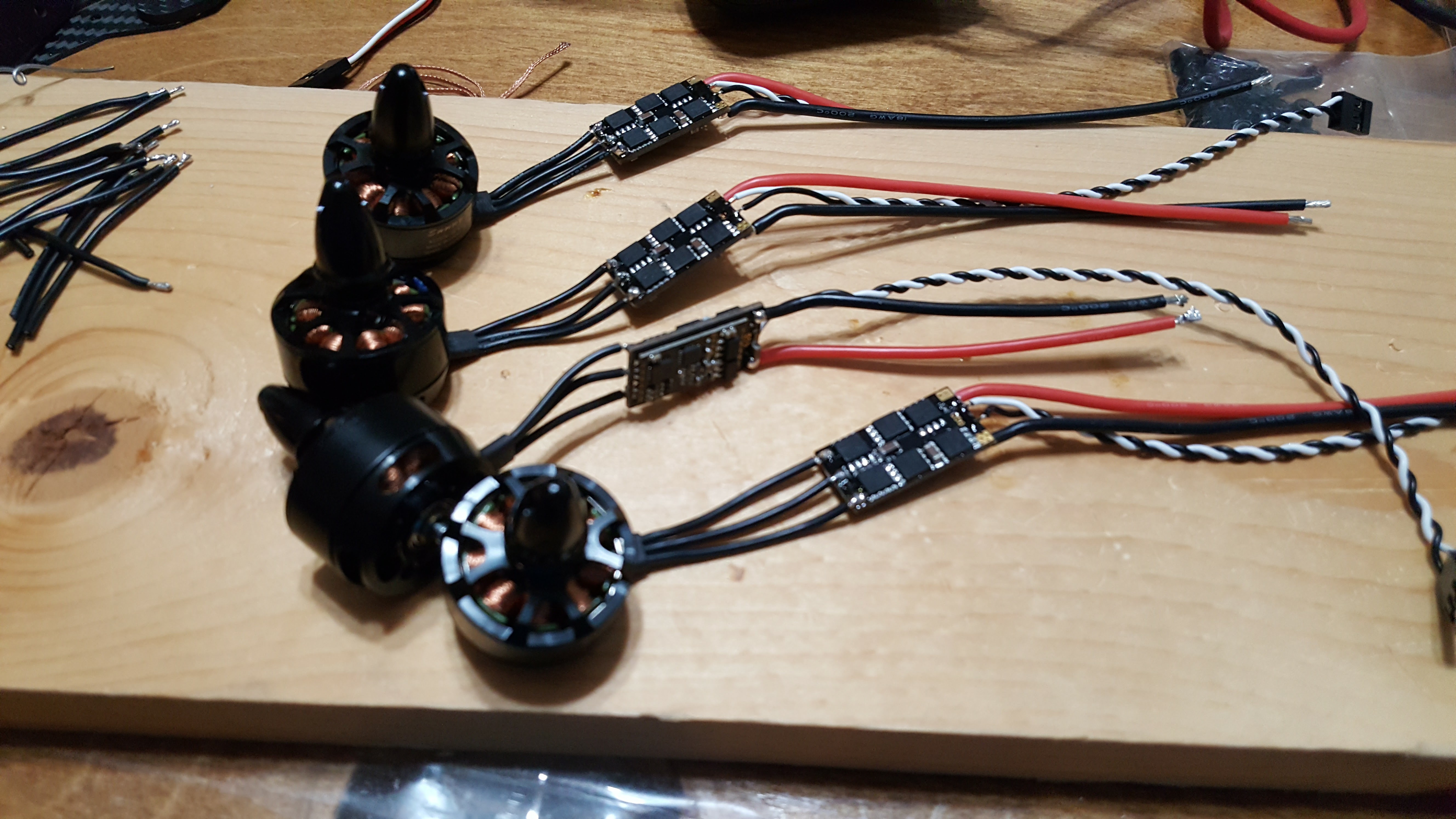
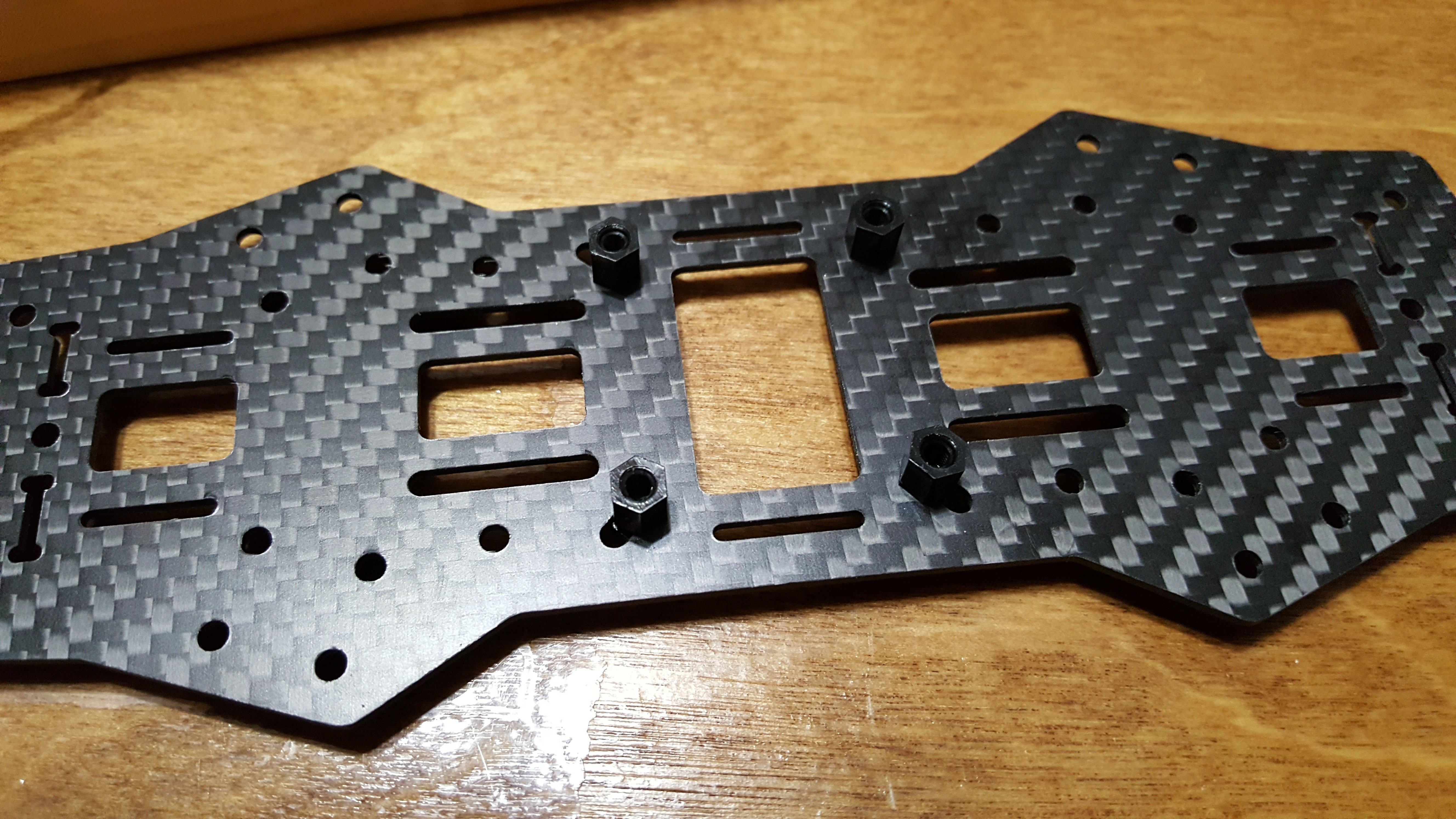
Now that the electronics are largely sorted out, it’s time to start putting everything together.  For the frame, I purchased a 250 sized carbon fiber frame off of amazon.  It’s probably a clone of the various QAV250 models.  Price was really good, and from what I can tell the components all look to be pretty decent.  The one thing lacking?  The instructions.  To say they were lacking would be somewhat charitable.  There was one page that had some somewhat english instructions on one side, and the other in what was probably chinese.  The real issue was that the diagram wasn’t real clear on exactly which pieces went through multiple layers and which didn’t.

First, we start off with the bottom, and mount the M3 sized nylon standoffs through.  It’s important to do this part first, because at least in my case, these standoffs only go through the first layer of the bottom, and the nuts aren’t very accessible after the bottom is completely assembled.  

20170128_133303

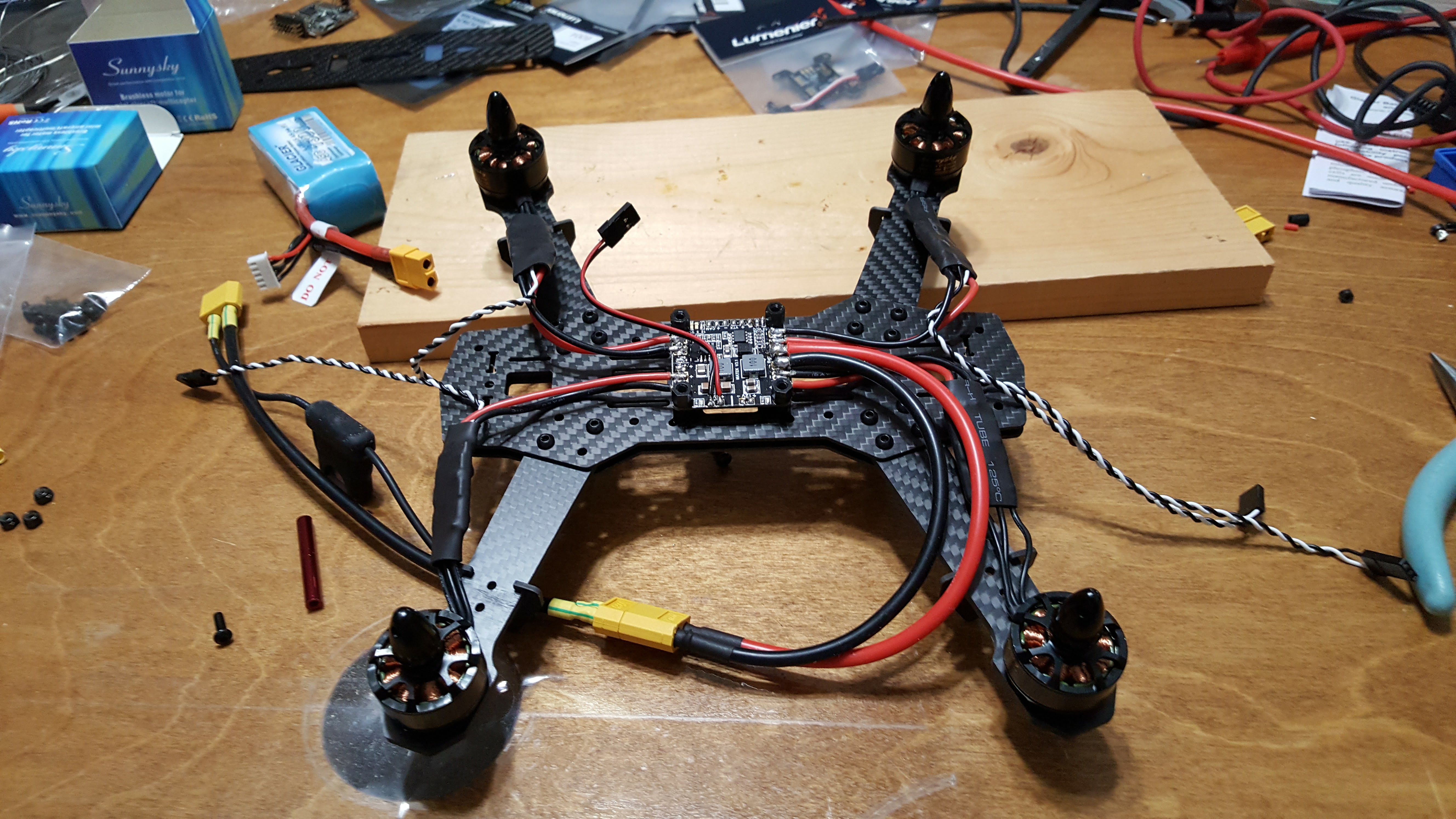
Next, the arms for the motors are mounted between the top bottom panel and the bottom bottom panel. 

20170128_135006

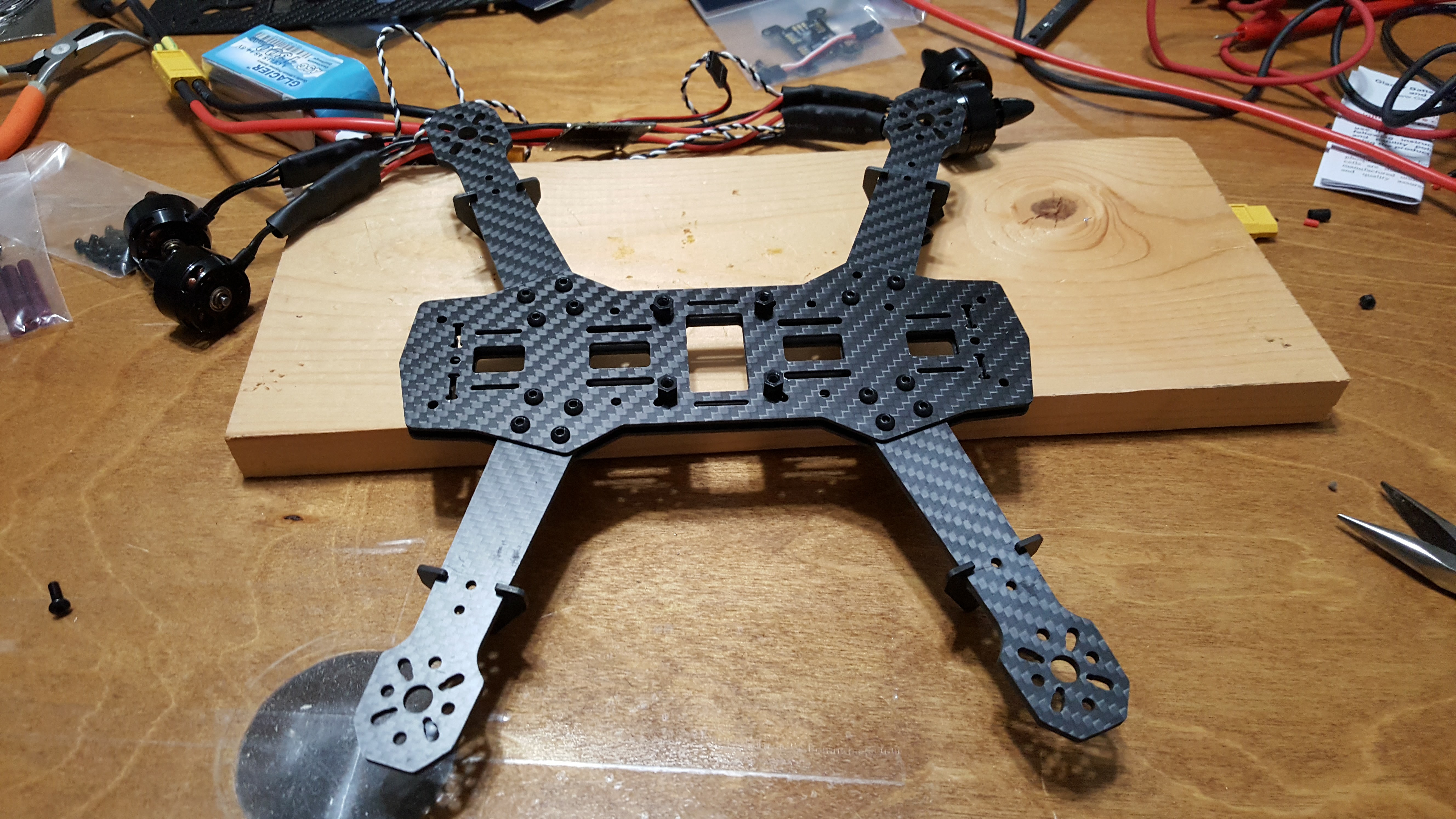
Then we can install the power distribution board, and the motors can be mounted to the arms.  Another set of M3 standoffs go on top of the power distribution board to be ready for the next board.

20170128_140839

Flashing the BLHeli_S firmware to the esc’s

20170127_230832

Ok, so first I installed the BL Heli Suite software on the computer, and then with all the esc’s connected to the flight controller, connected the software to the quad.  As you can see, when I read the setup it found all 4 of the esc units, which is good.

20170127_232838

This is where things were starting to get confusing.  My esc’s are ZTW Polaris 25A BLHeli_S Esc’s.  From what I could determine, these esc’s use the A-H-20 firmware.  By default, it wasn’t matching the A-H-20 when it was giving me a list of firmwares to select, and I had to turn off auto-matching.  Then, once I selected the correct firmware, I got this error message that was somewhat ominous.  After doing some more research, I was pretty confident that I was going in the right direction, so I hit ignore.  Which yielded an even more ominous warning:

20170127_232846

So that made me go back digging through all I could find as a reference.  However, I was still positive that I had the right firmware selected, so ultimately ended up flashing with the A-H-20 firmware.  Everything went well with that, and I was able to eventually configure the motor directions (which I apparently have no photos of), and then test that they would spin up.  So while it turned out to be a scary step with all the warnings, ultimately it worked out.

Smoke preventer

20170126_230607

I found the idea for this at the propwashed site – a site that I found very helpful as I was doing this first quad build.  Basically, the idea is that if you’re not using the motors on the quad, the power draw should be less than about 3 amps (and I’m guessing significantly less than that really).  However, if you have some sort of short due to bad wiring or soldering, you would get a sudden load of much higher than that.  The idea here is to that you put a 3A auto fuse into an auto fuse holder, and then connect this between your batter and the quad copter.  If something is wrong and it pulls more than 3 amps, then hopefully the fuse will blow before you damage the electronics.  I don’t have any pictures of me using this, but the first time I connected the quad to the battery, I did have this in place.  

First connection of flight board to the computer

20170125_234645

Ok, so the first time anything had any power through it.  I installed the betaflight software on my laptop, and connected the flight controller to the laptop.  Things worked pretty well and the flight controller was recognized.  I then went ahead and flashed the update to the controller so that it was at the current version of betaflight.  Maybe I’m easily amused, but I did find it kinda neat that on the page being shown, as I’d move the flight controller around, the image of the quad copter would also move in unison with the flight controller.  At least that means that the various sensors appear to all be working.

Shortening motor and esc wires

20170123_232237

After initially thinking that I’d leave all the wires at their original length, after I started comparing how things would fit onto the frame and how long all the excess wires would be I realized that it wasn’t going to be practical, so I shortened the wires from the motor to the esc and then from the esc to the power distribution board to something that would more reasonably work.