Receiver

Next, the receiver gets added.  I was starting to have problems finding a good spot to put things, so I decided that this would go on the bottom.  Not necessarily ideal, especially if I fly from somewhere where the grass is wet.  The feet on the legs do help lift it off the ground some though.  The antenna I routed up along the side of the fuselage to stick straight up.  I ended up using a cable-tie and some shrink wrap tubing to give it some rigidity, and then zip-tied it in place to the top plate of the quad.

20170202_204227

Stacking the boards

Time for more assembly.  The power distribution board had already been mounted in a previous step, so next I mount the led power distribution board.

20170201_232600

More stand-offs on top of that, and then the flight controller board.

20170201_234955

The wires from the various esc’s are plugged into the board into the above photo.  What you can’t see is that one of them is wired backwards, something I don’t figure out until later.

Finally, apply some power, and wow are those leds bright.

20170201_230427

LEDs

The next step was to add some led’s to the quad.  I bought this set of leds from getfpv.com.  They included a power distribution board, 4 sets of boards designed to be mounted on the arms that each have 4 leds on them, and a panel for the back of the quad with a 3×3 array of led’s.  The back panel also has the logic in it to allow for programming color sequences into the led’s.  That panel required soldering another set of pin headers onto it (which didn’t go that smoothly).  And then the wires from the power distribution boards to the arm leds all had to be soldered in place, 4 wires at each end.  These wires were a real pain in the neck to get soldered properly.  The wires are very fine, and the solder pads that you have to connect them to are small and close together.  Even with my fine tip soldering iron I had all sorts of trouble getting this done without screwing things up.  Unfortunately, my pictures of this phase pretty much turned out to be pretty blurry.  This is the best of the lot, showing the arm panels wired to the distribution board, but even it’s pretty blurry.

20170131_233616

Vertical support posts

If you’ll recall, I mentioned that the directions weren’t real clear on which pieces would go through both of the bottom panels and which wouldn’t.  I next went to add the vertical posts that the top plate mounts to and realized that the screws for these only go through the top layer of the bottom.  If you tried to run it through both, the screws would be too short, and you’d actually put some bending pressure on the bottom plates which wouldn’t be good.  So, had to remove the bottom layer of the bottom (and all the arms), and then mount the posts and put everything back together again.

20170130_233558

Beginning frame assembly

Now that the electronics are largely sorted out, it’s time to start putting everything together.  For the frame, I purchased a 250 sized carbon fiber frame off of amazon.  It’s probably a clone of the various QAV250 models.  Price was really good, and from what I can tell the components all look to be pretty decent.  The one thing lacking?  The instructions.  To say they were lacking would be somewhat charitable.  There was one page that had some somewhat english instructions on one side, and the other in what was probably chinese.  The real issue was that the diagram wasn’t real clear on exactly which pieces went through multiple layers and which didn’t.

First, we start off with the bottom, and mount the M3 sized nylon standoffs through.  It’s important to do this part first, because at least in my case, these standoffs only go through the first layer of the bottom, and the nuts aren’t very accessible after the bottom is completely assembled.  

20170128_133303

Next, the arms for the motors are mounted between the top bottom panel and the bottom bottom panel. 

20170128_135006

Then we can install the power distribution board, and the motors can be mounted to the arms.  Another set of M3 standoffs go on top of the power distribution board to be ready for the next board.

20170128_140839

Flashing the BLHeli_S firmware to the esc’s

20170127_230832

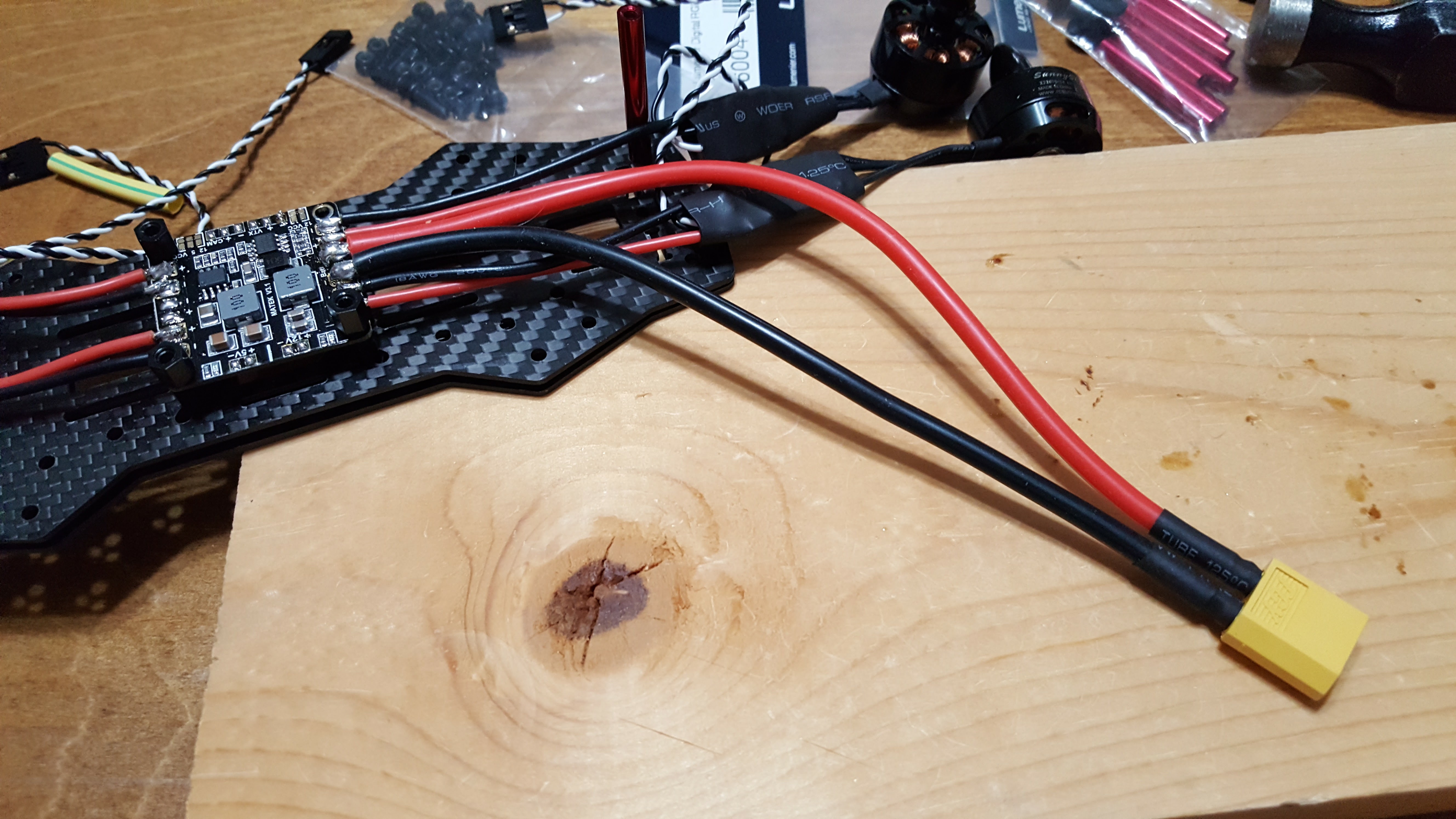
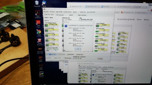
Ok, so first I installed the BL Heli Suite software on the computer, and then with all the esc’s connected to the flight controller, connected the software to the quad.  As you can see, when I read the setup it found all 4 of the esc units, which is good.

20170127_232838

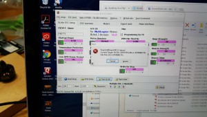
This is where things were starting to get confusing.  My esc’s are ZTW Polaris 25A BLHeli_S Esc’s.  From what I could determine, these esc’s use the A-H-20 firmware.  By default, it wasn’t matching the A-H-20 when it was giving me a list of firmwares to select, and I had to turn off auto-matching.  Then, once I selected the correct firmware, I got this error message that was somewhat ominous.  After doing some more research, I was pretty confident that I was going in the right direction, so I hit ignore.  Which yielded an even more ominous warning:

20170127_232846

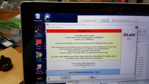
So that made me go back digging through all I could find as a reference.  However, I was still positive that I had the right firmware selected, so ultimately ended up flashing with the A-H-20 firmware.  Everything went well with that, and I was able to eventually configure the motor directions (which I apparently have no photos of), and then test that they would spin up.  So while it turned out to be a scary step with all the warnings, ultimately it worked out.

Smoke preventer

20170126_230607

I found the idea for this at the propwashed site – a site that I found very helpful as I was doing this first quad build.  Basically, the idea is that if you’re not using the motors on the quad, the power draw should be less than about 3 amps (and I’m guessing significantly less than that really).  However, if you have some sort of short due to bad wiring or soldering, you would get a sudden load of much higher than that.  The idea here is to that you put a 3A auto fuse into an auto fuse holder, and then connect this between your batter and the quad copter.  If something is wrong and it pulls more than 3 amps, then hopefully the fuse will blow before you damage the electronics.  I don’t have any pictures of me using this, but the first time I connected the quad to the battery, I did have this in place.